Your Source for DIY Pedal PCBs and NostalgiTone! › GuitarPCB Forum › General DIY Pedal Discussion › Use a 4PDT?
- This topic has 8 replies, 3 voices, and was last updated 4 years, 11 months ago by
 Anonymous.
-
AuthorPosts
-
July 11, 2021 at 4:30 pm #19677AnonymousInactive
is it possible to use a 4PDT to turn on/off two seperate effects in two seperate signal paths while still using an LED to indicate? like say you would have a delay in one path and a fuzz in the other, but you want to turn them both on or off simultaneously from one switch? I was googling around and can’t seem to figure out what lugs would go where, and most everything just refers to either an order switch (your’s most often!) or to a loop switcher that switches between two loops, which is cool but not quite what I’m trying to figure out.
July 11, 2021 at 5:12 pm #19678CybercowParticipantI always have to slow down my thinking when considering wiring most any switch.
The simplest bypass switch is a SPDT. The signal input goes to the center lug, and the other two lugs will go to the effect circuit input and the output jack. But mind you, that leaves the input of the ‘effect circuit dangling’ and its output is still also connected to the output jack.
If you’re OK with that, You can use a 4PDT toggle to switch two effects off and turn two LEDs on or off. Just use two of the poles for the effects, and the other two poles for the LEDs.
July 11, 2021 at 5:12 pm #19679AnonymousGuestYes. A 4PDT switch is really 4 switches. Each pole has 3 lugs . The middle lug is the common lug and the two adjacent lugs are the pathways for the signal. You select one of these depending on the position of the switch.
If you use one pole, or set of 3 contacts for selecting a status LED, you have three other poles that can be used to select 3 other circuit paths. That can be three other effects depending on how you wire it up.
July 11, 2021 at 5:15 pm #19681AnonymousGuestP.S. I also agree with Cybercow. We often post replies at the same time!
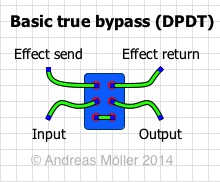
July 11, 2021 at 6:35 pm #19687AnonymousInactiveokay, Thank you for bringin it down a level. so if I think of the $PDT as a set of simpler switches, I naturally kind of lean this way and it still leaves questions. So in the below pic is the most basic of True Bypass wiring on a DPDT, if I think of the $PDT as just two DPDT’s side by side this makes sense. it provides two separate path inputs, two separate path outputs, and can access both effect paths.
where my confusion is is how to connect a single led to signal when the effects are on? as there isn’t another pole for use as is normally available in the 3PDT configuration…
July 11, 2021 at 7:04 pm #19688AnonymousGuestCybercow gave you the solution. Instead of using 2 poles to switch one effect’s IN and OUT connections, use only one pole to switch just the IN connection and leave the OUT attached. This may not always work because it may create an antenna for noise. But in many cases it will permit you to only use one pole for an effect.
July 11, 2021 at 9:00 pm #19689AnonymousInactiveAh!… now I’m understanding it better, rather than a true bypass it would essentially still leave that effect kind of “there” correct? I mean this isn’t an issue for me, but am I grasping it?
July 11, 2021 at 9:14 pm #19690AnonymousGuestYep!
July 11, 2021 at 9:26 pm #19691AnonymousInactiveWow that makes way more sense. I should have picked up faster when he was talking about SPDT, thank you Cyber Cow and Wilkie1!
-
AuthorPosts
- You must be logged in to reply to this topic.