Your Source for DIY Pedal PCBs and NostalgiTone! › GuitarPCB Forum › GuitarPCB Build Support › One Knob Fuzz – Novice
- This topic has 9 replies, 4 voices, and was last updated 2 years, 1 month ago by
 Billy.
-
AuthorPosts
-
March 28, 2024 at 10:28 am #31695AnonymousGuest
Hi Folks, Have just finished my first build and it’s not working. There is a signal on the by-pass but not when switched on. Can anyone spot any mistakes? I tried following instructions to the letter. Thank you.
March 28, 2024 at 2:14 pm #31698BarryKeymasterI noticed that you do not have a CLR current limiting resistor on the 3PDT wiring board.
That will not cause it not to work but it will blow out your LED. You need a resistor of any value between 2k and 4.7k
You installed it on the main board but since you chose to mount the LED on the wiring board and not the main board (This is an option for builders) you must have a CLR on the wiring board. If you have another resistor you can leave the one on the main board alone.
As for it not working I suggest that you re-flow the entire project by reheating the pads and make sure you have good solder joints.
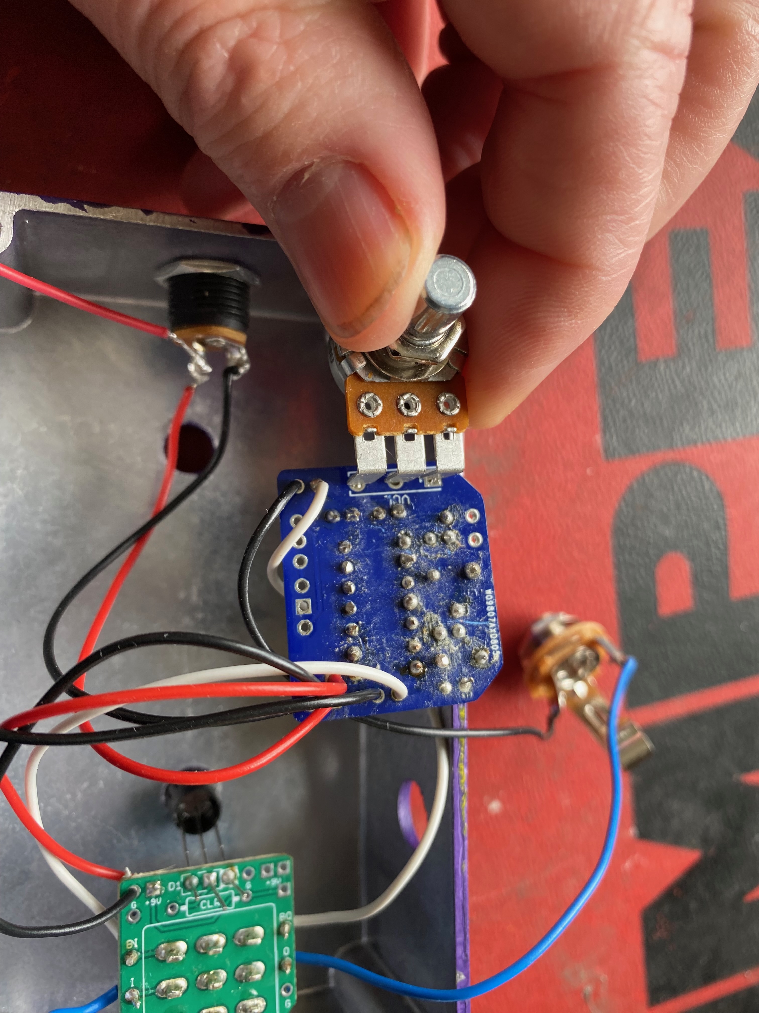
If you look at the photo these solder joints look dull and dry. Try reheating them for just a moment to reflow the solder and add a tiny bit of extra solder as needed. Also it looks like there is no solder in the middle pad of the Pot which is a very likely suspect. Reflow all of those.
Be careful not to burn out the pads or wiring. It looks like the heat is pretty high or you are not using a conical tip.

In this image it looks like the solder is just sitting on the potentiometer leads and not touching the pad. The solder needs to flow into the pads and be secure to the leads. A simple reflow with just a tiny bit of added solder will fix that quickly.
March 28, 2024 at 4:12 pm #31699AnonymousGuestThank you so much Barry. Very helpful. Will take your advice and see where it takes me. Tested the LED and it’s still working. I was using a conical tip soldering iron but it was taking some time to melt the solder, so, I switched to an ancient one I found in an old box from 40 years ago, it lacks a bit of subtlety but….. Very grateful for your help
March 29, 2024 at 7:00 am #31706Jeff24ParticipantIs the pot 180 degees off? per the build doc, the board-soldered pot should under the board, not outside it.
March 29, 2024 at 1:17 pm #31708BarryKeymaster@ Jeff24
Thanks for that input. That went right over my head. You are correct.
What would happen there is that it would work in reverse so when he is turning the volume up he is actually turning it down. I am not sure how his desoldering is but you could probably just leave it that way and find a nice spot in the rotation and just leave it like that since you are not going to be messing with it once you find the right volume.
There is a silkscreened (1) as well as a square pad on the PCB that indicates the lug number (1) of the potentiometer for the correct orientation.
April 4, 2024 at 11:31 am #31791AnonymousGuestUnfortunately, still not working, having tried all the above.
April 4, 2024 at 1:08 pm #31792BarryKeymasterWe are going to need some updated information to help.
- Do you get sound in bypass?
- Is there any sound at all with Volume turned either way in active mode?
- Are any of the pads burnt out?
- Post complete voltage readings of both Q1 and Q2 (C=, B=, E=) as well as voltage reading at the 9v pad. Place red probe on lead or pad to be tested and black probe on any circuit ground.
- If you changed Pot orientation make sure there is protection from a short on the solder side of PCB.
- Post clear photo of the newly flowed PCB solder side. (If you changed pot orientation bend pot back slowly)
- Post clear photo of solder side of the potentiometer.
- Post photo that best shows off-board wiring connecting In/Out Main board to 3PDT to In/Out Jacks.
Here is the datasheet image for measuring and reporting the correct voltages
Finally you can use this in tandem with your DMM to verify continuity to all pertinent connections making sure you have common grounds between 3PDT and Main board as well as Power. Also between In/Out throughout the path. Since you are not using “star grounding” method some connections do not apply.
For continuity check do this:
April 17, 2024 at 7:30 am #31940AnonymousGuestHi Barry,Apologies for slow reply and thank you for all your support.
- Yes there is a sound with the by-pass
- There is a buzz when switched on and the volume is working. The LED is also working
- It doesn’t seem to be
- Q1: E=0, B=0, C=9 . Q2: E=8.8, B=9, C=9.2. Not sure what you mean by the 9V pad ???
April 17, 2024 at 11:54 am #31941BarryKeymasterNot sure what you mean by the 9V pad ???
Ensuring continuity with the diagram provided and your DMM is crucial for identifying potential issues.
For instance:
Confirming a shared ground between both of the circuit boards and the power jack.
Validating the audio pathway from the main board to the wiring board and the appropriate input and output jacks.
Also note that while the Continuity chart does not show a 3PDT wiring board the connections are still the same.
So you will need to report on all continuity checks as well as the 9v pad readings.
April 17, 2024 at 11:30 pm #31960BillyModeratorWe need much clearer pics of your wiring it’s very difficult to trace anything
Post a pic looking down on the pcb so that all the wiring can be traced to the in and out jacks, DC jack etc
We can’t clearly see the DC jack wiring
A lot of your solder joints look like they may be potentially dry inside you don’t want any dull, grey or ball like joints
Some of your images are out of focus so it’s hard to see if there’s any damage to the pcb
Make sure you aren’t plugging your in cable to out jack and visa versa with the enclosure the wrong way up it’s a very common beginner mistake you’d still get bypass but no effect signal
All of your component values and orientation that I can see look correct
-
AuthorPosts


 Hi Barry,

- You must be logged in to reply to this topic.